We discussed the two types of Universal Peripheral Interfaces in embedded systems UART
and SPI in Chapter Ⅰ.
Now let’s learn about I2C, ADC, and CAN bus in Chapter Ⅱ.
I2C (Inter-Integrated Circuit) is a two-wire serial, half
duplex bus developed by Philips, mainly used for communication between chips at
close range and low speed. It is a widely used bus standard in the field of
microelectronic communication control. It is a special form of synchronous
communication, with advantages such as fewer interface lines, simple control
methods, and small device packaging.
I2C can transmit information between multi-master and
multi-salve nodes using only two wires: SDA (serial data) and SCL (serial
clock). The serial 8-bit bidirectional data transmission rate can reach 100 Kbit/s
in standard, 400 Kbit/s in fast mode, and 3.4 Mbit/s in high-speed mode. The device
connection is shown in Figure 1.

Figure
1 I2C Bus Master to Slave Connections
The data on the SDA line must be stable during
the high period of the SCL line. The HIGH or LOW state of the SDA line can only
change when the clock signal on the SCL line is low.

Figure
2 The Synchronous Data Signal
Start Condition: When SCL is HIGH
and SDA jumps from HIGH to LOW, the data transmission starts.
Stop Condition: When SCL is
HIGH and SDA jumps from LOW to HIGH, the data transmission stops.
Both the start condition and stop condition are
issued by the master devices. After the start condition is generated, the bus
is in an occupied state. And after the stop condition is generated, the bus is
released and in an idle state.
In an idle state, both SCL and SDA are at high
levels. The process is shown in Figure 3 below.

Figure
3 Start Condition and Stop Condition
Acknowledgment signal: after the 1-byte transmission is completed, that is, within the 9th SCL clock
cycle, the master needs to release the SDA bus and hand over the bus control to
the slave. Due to the role of the pull-up resistor, the bus is at a high level
at this time. If the slave correctly receives the data sent by the master, it
will pull the SDA down, indicating an acknowledgment signal.
Not acknowledgment signal:
When the 9th SCL clock cycle is reached, the SDA remains high, indicating a not
acknowledge signal.
Each byte must be guaranteed to be 8 bits. When
transmitting data, the highest bit (MSB) is transmitted first, and each
transmitted byte must be by an acknowledgment bit (i.e. a frame has a
total of 9 bits). If there is a not acknowledgment signal from the slave within
a certain time, it is automatically considered that the slave has received the
data correctly, and the master sends a stop condition to end the communication.
The data transmission format is shown in Figure 4.
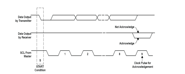
Figure
4 Data Transmission Format
I2C is usually used
for communication between MCU peripherals or multiple MCUs. The I2C interface has
the characteristics of simple hardware and easy software programming.
In instrument systems, it is often necessary to convert the detected continuously changing analog signals such as temperature, pressure, flow rate, speed, and light intensity into discrete digital signals before they can be input into a computer for processing. These analog signals are converted into electrical signals (usually voltage signals) through sensors, and after being amplified by amplifiers, they need to conduct certain processing to become digital signals. The device that converts analog to digital signals is commonly referred to as an analog-to-digital converter (ADC), abbreviated as A/D.
The process of A/D conversion is a process of sampling, holding, quantifying, and encoding. The basic idea of ADC is to compare the input analog voltage with the reference voltage (directly or indirectly) and convert it into a digital output. There are three types of ADC: parallel comparison type, successive approximation type, and double integration type.
When using ADC, the most important concerns are conversion accuracy and conversion time. The conversion accuracy is mainly influenced by external factors such as the stability of the power supply voltage and reference voltage, the stability of the operational amplifier, and environmental temperature. Factors affected by the chip itself include resolution, quantization error, relative error, linear error, and so on.
The full name of the CAN bus is Controller Area Network. It is a serial, synchronous, and half duplex bus. Developed by BOSCH Company in Germany, this peripheral interface is one of the most widely used field buses internationally.
The characteristics of the CAN bus are as follows:
The CAN communication protocol is as follows:
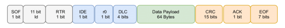
CAN specifies a total of 5 types of frames, also known as packets. Data frames are the most important and complex in CAN communication. The data frame starts with one explicit bit (logic 0) and ends with seven consecutive implicit bits (logic 1).
Carrier-sense multiple access (CSMA): Each node must listen to the bus before attempting to send a message. Only when the bus is idle it can be sent.
Collision Detection+Arbitration on Message Priority (CD+AMP): Resolves collisions through pre-programmed message priority by bit arbitration, with message priority located in the identification domain of each message. Messages with higher priority identifiers can always obtain bus access, which means that the last message in the identifier that remains logically high will continue to be transmitted because it has a higher priority.

Figure
5 CAN bus data frame
Standard CAN: Only an 11-bit
identifier is used to determine the priority of a message. The smaller the
value in this field, the higher the priority. As shown in Figure 6.
Figure
6 Standard CAN 11-bit Identifier
Extended CAN: A 29-bit identifier. As shown in
Figure 7.

Figure 7 Extended CAN 29-bit Identifier
The CAN bus mainly uses low-speed CAN (that is, ISO11898-3 standard) in the industrial control field and uses 125 Kbps high-speed CAN in the automotive field. The CAN protocol is widely used in all types of automotive industry applications, including passenger cars, heavy-duty trucks, and multi-purpose vehicles, as well as agricultural vehicles.
Most RF-star modules are embedded with UART, ADC, I2C, and I2S peripherals in hardware. Due to the market needs, UART is one of our most important communication modes in software. Almost all of RF-star’s BLE modules and Wi-Fi modules based on TI, Silicon Labs, Nordic, Realtek, and our self-develop ICs are featured with UART serial port protocol for transparent transmission in order to ease the integration development of the end products, shorten the development cycle, save the certificate qualification time and costs with certified modules, and more flexibility with more module RF designs. For example, these wireless modules are very welcome:
RF-BM-2642B1, RF-BM-BG22A1, RF-BM-ND04, RSBRS02ABR, RF-WM-20CMB1
Shenzhen RF-star Technology Co., Ltd. (RF-star) is a high-tech company focusing on radio frequency devices and has been the official third-party IDH of Texas Instruments for more than a decade. RF-star provides IoT wireless modules and a full set of solutions, including BLE, Wi-Fi, ZigBee, Thread, Matter, Wi-SUN, Sub-1G, etc. For more information, kindly visit the official website https://www.rfstariot.com/ or contact us at info@szrfstar.com.
Shenzhen HQ: Room 503, Podium Building No. A-12, Shenzhen Bay Science and Technology Ecological Park, Nanshan District, Shenzhen, Guangdong, China, 518063
Chengdu Branch: N2-1604, Global Center, North No. 1700, Tianfu Avenue, Hi-Tech District, Chengdu, Sichuan, China
Tel : +86 (0)28-86925399
Email : info@szrfstar.com
Teams : Sunny Li
Whatsapp : +8618190842785